Create PDF To Save Offline


rainman watermakers logo


Rainman Technology Pty Ltd
36 Sydenham Road
Brookvale, NSW 2100
Australia


www.rainmandesal.com


support@rainmandesal.com


Introduction

This instruction guide is for the installation of our Modular watermaker range. We offer a variety of options in terms of power types and outputs, but the principles in this document are standard across them all.

More technical information can always be found on the support section of our website.

Several icons are used throughout the text to indicate the purpose of the particular paragraph:

The 100L icon means the paragraph applies specifically to the largest 100lph system.

The 140L icon means the paragraph applies specifically to the 140lph (either 230VAC/50Hz or 115VAC/60Hz).

The 240L icon means the paragraph applies specifically to the largest 240lph Torrent system.

The 140L/100L icon means the paragraph applies specifically to the 140lph and 100lph units (either 230VAC/50Hz or 115VAC/60Hz).
This icon indicates a specific warning, indicating actions to be taken to ensure safety or protection of your watermaker.

System Layout

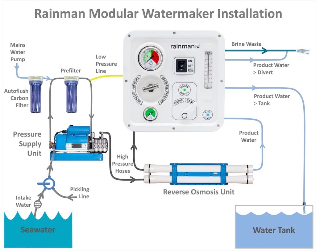
The Modular Rainman watermaker is designed for a minimalist installation, with key components mounted in space efficient locations. The main mounting of hardware includes the pressure supply unit (PSU), reverse osmosis (RO) unit, the optional control panel, and a couple incidental items. The plumbing will include related seawater intake hoses, two high pressure hoses, some fresh water plumbing, and a brine waste. Electrical will be the main power (either AC or DC) and if you have either of the optional control panel (Manual or Auto) it will be low power 12-24VDC.

rainman modular watermaker installation schematic

Control Panel Option

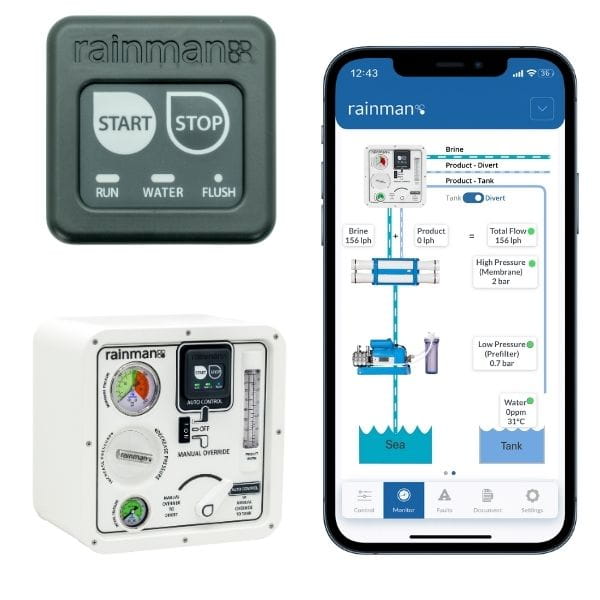
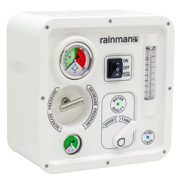
Most Modular Rainman installations will incorporate either the Manual or Automated Control panel to enhance the user experience. Each of these has its own special considerations, so please review the specific user guide that applies to your configuration.

Auto Control Panel User Guide

Manual Control Panel User Guide

Video Tutorial

To gain some preliminary understanding of your Rainman Modular system installation, watch the below videos.

Rainman Installation guide

Excellent install video from Sail Life

Installation Fittings

Rainman Modular watermakers are shipped with most of the plumbing fittings required for installation. Most of the systems utilise the same fitting kits, but the AC 240L Torrent has higher flow rates and has larger fittings.

All boats are somewhat different, so there may still be fittings required for a given installation. There may also be extra fittings from the Rainman kit that go unused. The plumbing installation kit can be broken into four main categories:

  1. Intake fittings required for seawater to get to the prefilter. A pickling line is also needed for long term storage.
  2. Brine waste fittings for most of the seawater flow and all of the salt to get back overboard.
  3. Product water fittings are required for getting water into a tank, with an option for a second tank or a testing tube. 
  4. Hoses are required for each of the above fittings to connect to the main watermaker.

The table below shows the fittings that are included with the system for any of the three framed options.

Select Tab For Your Model

The 140L/100L icon means the paragraph applies specifically to the 140lph and 100lph units (either 230VAC/50Hz or 115VAC/60Hz).

rainman watermaker plumbing intake

Seawater Intake
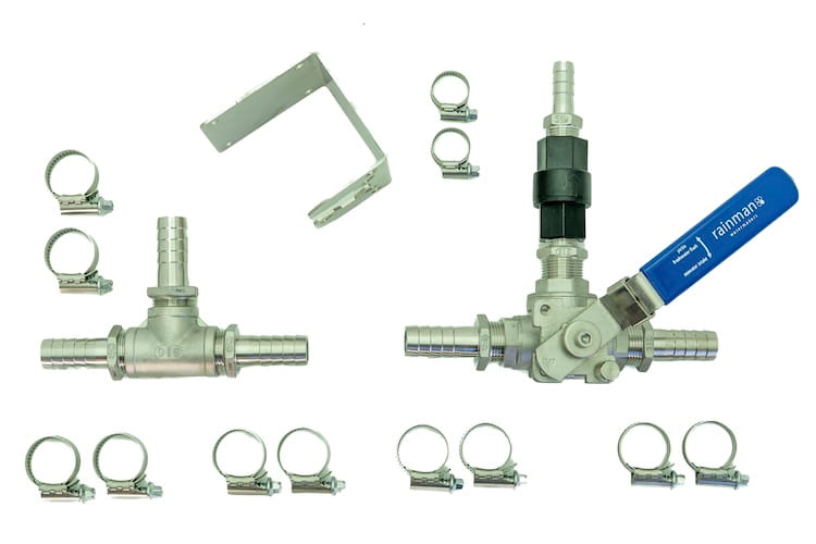
5 x ¾” hose barbs
1 x ½" hose barb
1 x ¾” BSP tee female
1 x ¾” BSP 3 way valve 316 S/S
1 x ½" check valve
12 x Hose clamps
1 x ¾”-½” hex nipple
1 x mounting bracket for 3 way valve

Rainman Intake Plumbing
Rainman Brine Waste Fittings

Brine Waste
2 x ¾” hose barbs
1 x 10mm push-fit
1 x 8mm push-fit
2 x ¾” BSP tee female
1 x ¾" joining nipple
2 x ¾”-¼” bush
4 x Hose clamps

Rainman Brine Waste Fittings
Rainman Product Water Fittings

Product Water
1 x Plastic 3 way valve (diverter valve)
2 x 8mm push-fits
1 x Roll teflon tape

Rainman Product Water Fittings

Installation Hoses
5 metre (16 ft) x ½” ID Intake Hose
6 metre (20 ft) x 10mm OD Brine Waste Hose
18 metre (60 ft) x 8mm OD Product Water Hose

The 240L icon means the paragraph applies specifically to the largest 240lph Torrent system.

rainman watermaker plumbing intake

Seawater Intake
5 x 1” hose barbs
1 x ¾" hose barb
1 x 1” BSP tee female
1 x 1” BSP 3 way valve 316 S/S
1 x ¾" check valve
12 x Hose clamps
1 x 1”-¾” hex nipple
1 x mounting bracket for 3 way valve

Rainman Intake Plumbing

Brine Waste
2 x 1” hose barbs
1 x ½” hose barbs
1 x 10mm push-fit
2 x 1” BSP tee female
1 x 1" joining nipple
1 x 1”-¼” bush
1 x 1”-½” bush
8 x Hose clamps

Rainman Brine Waste Fittings

Product Water
1 x Plastic 3 way valve (diverter valve)
2 x 10mm push-fits
1 x Roll teflon tape

Rainman Product Water Fittings

Installation Hoses
5 metre (16 ft) x ¾” ID Intake Hose
6 metre (20 ft) x ½” ID Brine Waste Hose
18 metre (60 ft) x 10mm OD Product Water Hose

Physical Installation

Pressure Supply Unit

Planning Installation

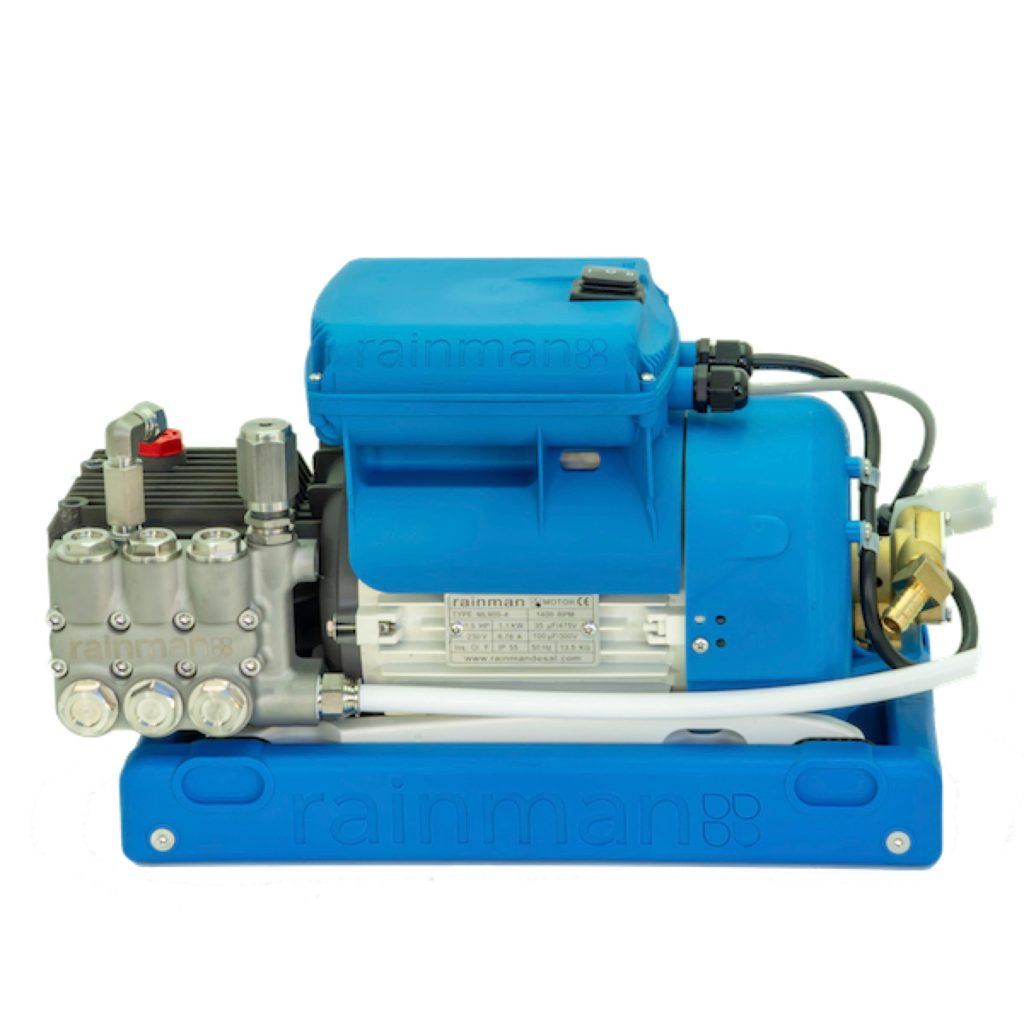
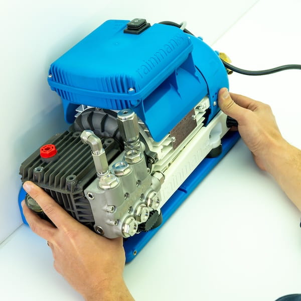
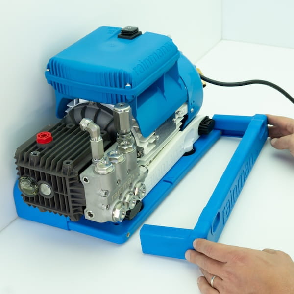
The mounting system for the Modular PSU has three parts. The mounting seat on the base and two mounting frames, one on each side.

rainman modular ac watermaker
mounting bracket rainman desalinator

The PSU needs to be correctly oriented when placed in the mounting assembly. The embossed diagram on the seat shows the correct orientation. The two side frames are labelled A or B, and must be used on the correct sides of the base seat. There are notches to prevent you from installing them on the incorrect side.

watermaker bracket detail rainman

When selecting a suitable mounting position, consider the following points:

  • The mounting kit should be secured to a level surface and positioned in such a way that there is a minimum 100mm (4”) of clearance on each side and have adequate ventilation.
  • Ensure the mounting surface is capable of supporting the system weight and take 20mm (⅞”) self tapping screws.
  • Each hose run between the PSU and the pre-filter should be no more than 2 meters (six feet).
  • Ensure that both the high pressure output fitting and the on/off switch are accessible.
  • The motor on PSU is air cooled and has a fan to push air over the motor. The motor is rated to stay under its max operating temperature in a max surrounding air temperature of 40°C (104°F). If the unit is mounted in an enclosed space without adequate ventilation, the air in the space will heat to over 40°C (104°F) very easily. If you are mounting the PSU in an enclosure with other machinery (e.g. in an engine room), it is very important to ensure that the ambient temperature remains below 40°C (104°F) whilst your watermaker is running concurrently with other machinery.

Instructions

  1. Before you fasten the mounting seat to the surface, attach the frame to the seat on the side that will have the least clearance when the unit is installed. Use two of the countersunk M6X20mm machine screws supplied for this.
rainman desalination bracket mount system
  1. Fasten the mounting seat to a level surface using all four holes. Use the self-tapping screws provided, or your choice of alternate fastener.
mounting bracket drill down
  1. Slide the PSU into the mounting seat as shown. Ensure the PSU orientation matches the embossed diagram on the mounting seat.
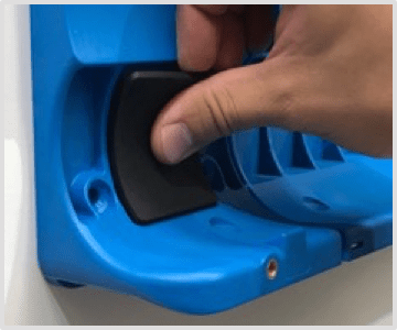
  1. As you place the unit in the mounting seat, taking care to align the black rubber vibration isolators on the PSU with the corresponding holes in the side frame.
rainman vibration isolation
  1. Slide the other mounting frame onto the mounting seat, taking care to align the holes in the frame with the black rubber vibration isolators on the PSU. This may require lifting the PSU slightly.
  1. Fasten the side rail to the mounting seat using the remaining two countersunk machine screws.
  1. Mount the prefilter bracket as close to the PSU as possible, not exceeding two meters (six feet). Before installing the prefilter, consider how you will run the tubing to the ‘IN’ and ‘OUT’ sides of the prefilter. It is very important that the tube from the brass lift pump runs to the “IN” side and the tube from the “OUT” side runs to the high pressure pump. Note that the screws mounting the bracket to the wall are larger than the ones mounting the housing to the bracket.
  1. Using the white ½” tube supplied, connect the ‘IN’ side of the prefilter to the corresponding fitting on brass lift pump on the PSU. Now connect the ‘OUT’ side to the push fitting on the side of the high pressure pump.
rainman prefilter mount
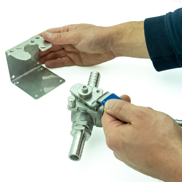
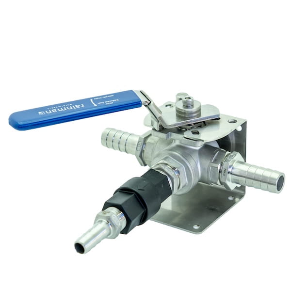
  1. Mount the bracket for the intake hose 3 way valve between the intake strainer and the lift pump. This will be used when pickling your system for long term storage, so space to use a bucket for drawing up pickling solution will be required.
  1. Replace the oil travel plug in the black high pressure pump with the breather plug.

Failure to use the breather plug will eventually lead to oil and or water leaks in the high pressure pump as it heats up during use.

Reverse Osmosis Unit

Planning Installation

The mounting system for Rainman RO High Output (twin 40” membranes) or Economy (single 40” membrane) are the same and consist of three parts. One back bracket and two mounting saddles. The Compact unit (twin 21” membranes) consists of four parts, including two abbreviated back brackets and two mounting saddles.

rainman reverse osmosis mounting bracket
rainman compact reverse osmosis mounting bracket

The RO units can be mounted either horizontally or vertically.

rainman watermaker naked mounted
rainman watermaker compact naked mounted
rainman watermaker naked vertical mounted

Instructions

  1. Fasten the back bracket using the appropriate fasteners. It is usual to mount against a wall, but the back bracket also has angled holes for mounting on a floor if desired. If you have a Compact RO unit (2 x 21” membranes), the abbreviated back brackets should be mounted 250mm (10”) apart as in the photo above. The lower part of the back bracket extends further so you can rest the RO unit while attaching the mounting saddles.
rainman naked ro installation
rainman naked desalinator installation
  1. Ensure all four rubber pads are in place.
rainman watermaker pads
  1. Place RO assembly in the back bracket. Note that the Economy RO unit (single 40” membrane) will only occupy one slot in the mounting bracket.
rainman watermaker ro installation
  1. Secure the RO unit by attaching the two saddles firmly using the four M6 x 40 cap screws provided.
rainman desalination mounting brackets
  1. Use slots on the back bracket with zip ties to tie off hoses, keeping the set up tidy.
rainman fresh product water lines
  1. Mount the product water flow meter at a convenient location in line with the white product water hose. Two screws hold the bracket in place and the flow meter itself slots in. The hose from the RO unit inserts into the bottom of the flow meter push-fit connector. The hose from the top of the flow meter connects to the product water three way valve.
rainman water flow meter

The vast majority of Modular Rainman installations will incorporate either the Manual or Automated Control Panels. This final step is only required for a minimalist installation without either of the control panels.

  1. Mounting the pressure control valve / gauge assembly can be up to 5 meters (15 ft) away from the RO unit. This configuration allows for a minimalist installation or integration with a broader control function. It provides significant flexibility on how to physically install the assembly, as per sample images.
rainman watermaker minimum installation
rainman watermaker naked mount
rainman desalinator locker mount

Plumbing

Product Water – Divert

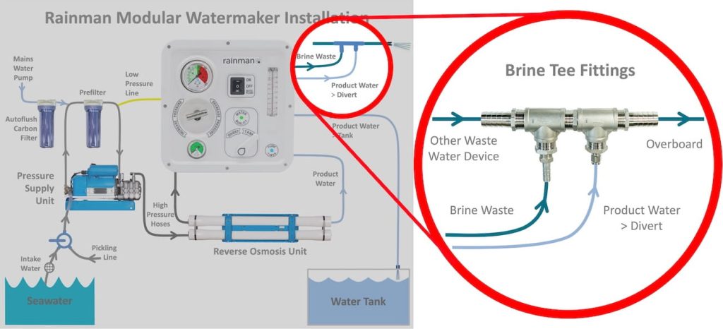
  1. Cut length of white product water hose and connect to rear of control panel marked “PRODUCT DIVERT”. Connect this line to either a tasting/sampling connection or tee it into the brine waste line..

Product Water – Tank

  1. Cut length of white product water hose and connect to rear of control panel marked “PRODUCT TANK”. Run this line into your fresh water tank. Two push-fits are included in the installation kit for connecting to your tank.

Product Water – Options

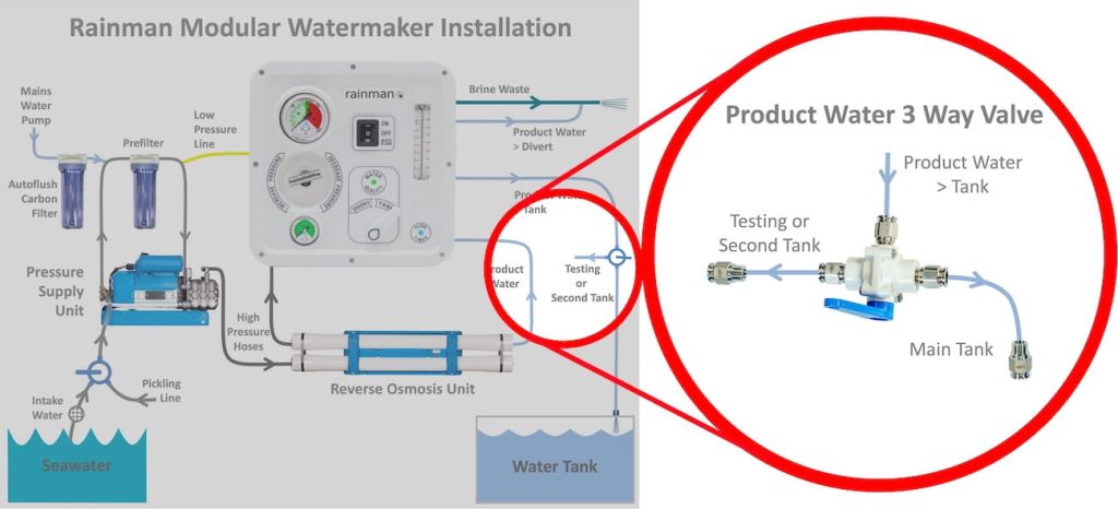
An extra 3 way valve for the product water is included to configure a testing port or to fill a second tank. This can be run off either the “Divert” or “Tank” line from the control panel. Additional 3 way valves can be used for further flexibility if required.

It is recommended to include a way to manually test the product water.

rainman modular installation fresh water

Extra Product Water 3 Way Valve

Brine Waste

  1. Cut length of brine waste water hose (braided clear for 240L, green for 140L or 100L) and connect to rear of control panel marked “BRINE OUTPUT”. Run this line to overboard waste.

Brine Waste – Options

Two tees are provided in the brine waste plumbing kit to allow for teeing both the brine and product water divert in to existing waste water line. This is recommended as the simplest configuration.

rainman modular installation brine

Brine Waste Tee Into Existing Line

Intake Hose
  1. Connect intake water hose to the input of the bronze lift pump. The check valve should maintain prime in intake line. Ensure you secure with double hose clamps. The third leg of the 3 way valve is used for pickling. Pickling instructions are in operations manual.
watermaker lift pump
watermaker boost pump intake

Autoflush

The autoflush valve connects to the vessel’s fresh water pump. Since a wide variation exists in configurations, hardware is not supplied. The below instructions are a sample of one way to configure the autoflush supply. The autoflush valve is supplied with a ½” BSP female connection.

The supply pressure should not exceed 3 bar (43 psi) or the lift pump’s shaft seal may begin to leak. In such cases, a 20 to 30 PSI pressure regulator should be employed.

  1. Connect mains pump water supply to autoflush motor valve.
watermaker autoflush valve

Electrical Connections

AC Supply

Select Tab For Your Model

Specific wiring info for torrent

  1. Have qualified electrician wire the system accordingly. Recommended wiring of at least 4mm².
watermaker wiring block
Rainman frame torrent wiring
  1. Rainman Frame-AC-240L-Torrent system incorporates dual voltage AC motor which allows the operations of the same machine on the boats of different AC power setups.
  2. All Rainman Frame-AC-240L-Torrent system motors are shipped wired for high voltage (220-240V).
  3. If low voltage (110-120V) is required, the diagram printed directly on the motor shows how the motor should be wired.
  4. Ensure power is disconnected prior commencing work with electrical wiring.
  5. Wires to be re-configured are behind the lid on the smaller terminal box on the side of the motor. The box on top of the motor is motor capacitor enclosure and does not require to be opened.
  1. For reference, the Frame-AC-240L-Torrent motor schematics, showing the low voltage and high voltage configurations.

Specific wiring for AC 140L and 100L systems

  1. A qualified electrician should hard wire the power via a Type C breaker.
    230VAC/50Hz – 10 Amp
    115VAC/60Hz – 20 Amp

Specific wiring for AC 140L and 100L systems

  1. A qualified electrician should hard wire the power via a Type C breaker.
    230VAC/50Hz – 10 Amp
    115VAC/60Hz – 20 Amp

Use a qualified electrician for AC wiring. The installation shall include a means of disconnection from the supply mains with contact separation in all poles, suitable for overvoltage category III conditions, in accordance with the wiring rules.

If the supply cord is damaged, it must be replaced by the manufacturer, its service agent, or similarly qualified persons in order to avoid a hazard.

DC Supply

  1. The red and black wires on the Duetsch plug should be connected to a 12-24VDC battery source. This provides power for the control panel. Using a DC power source that is not directly from a battery may add slight noise and interfere with accuracy of the sensitive salinity sensor.

Rainman Watermaker Installation Guide


rainman watermakers logo


Rainman Technology Pty Ltd
36 Sydenham Road
Brookvale, NSW 2100
Australia


www.rainmandesal.com


support@rainmandesal.com


Introduction

The Rainman installation system consists of parts that will allow you to install your AC electric or 12VDC watermaker. This is a guide only. Installation will vary from vessel to vessel.

All electric Rainman systems can be installed. The systems in the traditional blue case can be either installed or run as portable. The Rainman Modular systems are specifically designed for a minimum footprint installation.  The plumbing hardware described in this manual is included with a Rainman Modular system, or available as an optional item for the classic Rainman system in a blue case.

A system installation can be divided into the physical installation process and then plumbing the system into your vessel.

The mounting system is moulded from rugged fiberglass filled nylon and has been designed to make the physical installation of your system as quick and easy as possible. The white blemishes that may exist on some parts are normal residual from the moulding process.

Plumbing Into Vessel

Schematic

Below is a plumbing schematic of the Rainman modular system with control panel and autoflush options. The automated control panel configuration is the same.

Rainman Modular Schematic

Plumbing Overview

Regardless of whether you have a Rainman Modular system or the Portable Rainman in the blue case, the process of plumbing it into your vessel is the same. The plumbing installation is broken into five stages.

  1. Seawater intake
  2. Filters – sediment and activated carbon
  3. High pressure lines
  4. Brine outlet (waste over board)
  5. Product (fresh) water connection to fresh water tank

Stage 1 – Seawater Intake

The installation kit provides enough hose clamps to double clamp each hose barb.  You will need to use sealant (example SikaFlex or similar) on each hose barb before connecting hoses. The PVC sleeve on the intake 3 way valve is reversible to accurately reflect the orientation.

rainman desalination intake valve sleeve

Option 1 – Dedicated Through Hull

If you already have a spare through hull or plan to install a new 3/4” through hull fitting (1″ for 240L Torrent) with valve for your Rainman seawater intake, follow these steps to complete the intake install.

  1. Make sure the through hull fitting and valve are 3/4” inner diameter (1″ for 240L Torrent).
  2. Connect the intake hose non-return valve from the PSU to the middle port of the 3 way valve. Use thread sealant to ensure no leaks.
  3. You will need a sea strainer fitted directly to or off the 3/4” valve (1″ for 240L Torrent). This is not supplied by Rainman.
  4. Plumb the 3 way valve supplied from the sea strainer to the seawater intake port of the 3 way valve.
  5. Connect a loose hose to the fresh water / pickle intake.

Intake Hose – Options

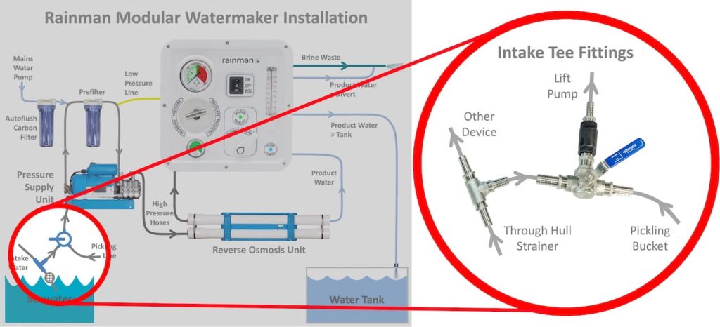
Although dedicated thru hull is preferred, it is possible to share a thru hull via a provided tee. Ensure watermaker is not forced to compete for water when operating.

rainman modular installation intake

Intake Hose Tee To Shared Line

If sharing a through hull via a tee fitting, ensure your watermaker is not competing for water while operating. This will starve the HP pump of water, cause cavitation, and damage your pump.

Stage 2 – Filters – Sediment and activated carbon


The brine waste water hose will come from the RO unit in the portable version of the system. If you have a Rainman Modular system, the green brine hose will come from the remote pressure control valve / gauge assembly.

Run the green brine hose from the RO unit to an above water through hull fitting, cable tying along the way to secure.  Parts are supplied so you can easily connect to an existing 3/4” hose connected to an above water through hull fitting.  Tee into the existing 3/4” hose with the tee supplied and plug the green brine hose into the brine push-fit (Port D).

If you have a spare above water through hull fitting, you may need to source parts to connect to the 1/4” – 10mm push-fit.

Stage 2 – Brine Outlet (Waste Overboard)

2 x 3/4” hose barbs
1 x 3/4” BSP tee female
1 x 3/4”-1/4” bush
1 x 1/4” – 10mm push-fit
4 x Hose clamps

The brine waste water hose will come from the RO unit in the portable version of the system. If you have a Rainman Modular system, the green brine hose will come from the remote pressure control valve / gauge assembly.

Run the green brine hose from the RO unit to an above water through hull fitting, cable tying along the way to secure.  Parts are supplied so you can easily connect to an existing 3/4” hose connected to an above water through hull fitting.  Tee into the existing 3/4” hose with the tee supplied and plug the green brine hose into the brine push-fit (Port D).

If you have a spare above water through hull fitting, you may need to source parts to connect to the 1/4” – 10mm push-fit.

rainman watermaker brine discharge

Stage 3 – Product (Fresh) Water Connections

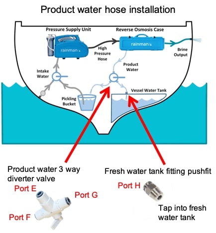
1 x Plastic 3 way valve (diverter valve fresh water tank and for testing)
1 x 8mm push-fit

  1. Run the white product water hose from the RO unit to your fresh water tank, cable tying along the way to secure.
  2. Tap the 8mm push-fit into the tank and push the end of the white product water hose into the push-fit (Port H).
  3. In a convenient place, cut the white product water hose and install the 3 way valve by pushing one side of the hose into the “in” (Port E) and the other side into the “out” (Port F) In the other out port (Port G) connect a loose hose (this loose end will become your testing hose).

Use a sharp knife to cut the white product water hose.  Make sure the hose is cut straight to ensure correct fitting into the push-fit fitting.

The white product water hose can be plumbed different ways, such as:

  1. Direct to your fresh water tank by tapping the supplied fitting as described above.
  2. Connecting it to the filler hose to your fresh water tank.
  3. Leave the white product water hose loose and manually putting it into your deck filler each time you use your Rainman watermaker.
rainman watermaker product water plumbing

Extra Items That May Be Required

There are some items you may require for your installation that are not part of the plumbing installation kit.

  1. Sea strainer
  2. Extra 3/4” hose
  3. 3/4” through hull fitting and valves

Autoflush Programming (Manual Control Only)

The framed system has an integrated autoflush system. Programming the system is quite simple and can be performed by accessing the small silver flush timer box inside the frame.

Flush Cycle Duration

The flush timer box is programmable from two minutes to eight minutes, in two minute increments. Eg: 2, 4, 6, or 8 minute flush cycle durations.

Press and hold the button for 2.5 seconds to go into programming mode. While holding the button down, a single green flash will indicate when to release the button. After releasing the button, a few rapid green flashes will indicate you are in flush cycle programming mode. The green LED will then flash twice for 2 minute flush duration, four times for 4 minutes, six times for 6 minutes and eight times for 8 minutes. After the green LED flashes 2, 4, 6, or 8 times, pressing the button selects that particular flush duration. The timer then exits programming mode and the green LED will flash the number of minutes in which the flush timer is set before re-entering countdown mode. At this point, the blue LED flashes according to the number of days remaining in the countdown. It remembers where it was at in the countdown. If you do not select any time while in programming mode, the timer will eventually revert back to countdown timer mode, resuming the most recent flush duration setting.

rainman autoflush programming mode

Example: To set a four minute flush duration

  1. Long press the flush timer button for 2.5 seconds. Release after green LED flashes once.
  2. The green LED will quickly flicker for one second, then off for one second.
  3. The green LED will start its flashing sequence, wait for the four flashes to appear, then press the button.
  4. The green LED will again quickly flicker for one second, then off for one second.
  5. The flush timer will respond by flashing the green LED four times, then a pause, then flash four times again. This allows the operator to verify the new setting is correct.
  6. The Rainman flush timer will now switch back to normal countdown operation, and the seven day countdown resumes where it was prior to programming.
  7. To test the new flush duration, press the push button again to initiate a flush cycle. After the flush cycle, the timer will reset to seven days.

Determining how long to set flush duration, consider that you will want approximately 10 litres (~2.5 gallons) of water to be pushed through the system on each flush cycle. The best way to determine this is by measuring the brine discharge during a flush cycle and programme the timer accordingly.

Flush Cycle Countdown

The flush cycle countdown time is designed to be fixed at seven days. This cannot be changed.

Electrical Connections

Select Tab For Your System Type
  1. Have qualified electrician wire the system accordingly. Recommended wiring of at least 4mm².
  1. A qualified electrician should hard wire the power via a Type C breaker.
    230VAC/50Hz – 10 Amp
    115VAC/60Hz – 20 Amp

Use a qualified electrician for AC wiring. The installation shall include a means of disconnection from the supply mains with contact separation in all poles, suitable for overvoltage category III conditions, in accordance with the wiring rules.

If the supply cord is damaged, it must be replaced by the manufacturer, its service agent, or similarly qualified persons in order to avoid a hazard.

Extra Level Of Membrane Protection

This section specifically applies to charter vessel owners, but can be useful for others as well.

In normal Rainman operation, the operator slowly increases pressure when starting to make water, then slowly decreases pressure when finishing. If power is inadvertently cut off from the Rainman (eg. turning off generator), pressure will drop quickly. While this is not best practice, it is unlikely to damage the membranes. However, if power is applied again before opening the pressure control valve, there will be a strong pressure surge that can damage the membrane.

If this is a risk in your vessel, we recommend installing a “no volt release switch” as an additional level of protection. When configured correctly, it will require a manual reset if a loss of power occurs. A note can be kept by the switch to remind the user to open the pressure control valve before resetting. This is not a Rainman part, but options are commonly available through your electrician (click here for example image).