

 Create PDF To Save Offline

Rainman Technology Pty Ltd
49 Orchard Road
Brookvale, NSW 2100
Australia
www.rainmandesal.com
support@rainmandesal.com
Introduction
The Rainman induction motor in an AC pressure supply unit (PSU) is a dual capacitor (capacitor start capacitor run motor). This means it has two large capacitors in the case above the motor windings. One for normal running of the motor and one only used during the startup. These are not considered consumable items and should last for many years. However, on very rare occasions, the electrical components may fail earlier. Run and start capacitors are inexpensive items and can be easily replaced. This manual is designed to assist in the procedures to change the capacitors.
WARNING: AC powered equipment can be very dangerous to work on, even if unplugged. It is highly recommended that repairs are executed by a licensed electrician. This manual is provided in case field repairs are required. If you would like assistance with this procedure, please contact Rainman or one of our many dealers around the world.

Motor Overview
This section provides a very high level overview how the capacitors affect the motor operation. It is not comprehensive, but intended to make the reader appreciate the function and importance of the start and run capacitors.
Run Capacitor
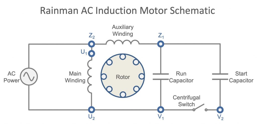
The run capacitor is wired into the auxiliary winding circuit and has two primary functions. First is that it ensures the auxiliary winding current remains 90° ahead of the main winding current, allowing for maximum torque on the rotor. Secondly, it keeps the overall combined current of the motor nearly in phase with the voltage. This makes the power factor near unity so the motor is most efficient.
Start Capacitor
As its name implies, the start capacitor exists to assist the motor in getting up to normal operating speed. It is only in the circuit until the motor gets to approximately 75% of its operating speed, when a centrifugal switch opens and the capacitor is disconnected. The start capacitor has the effect of further increasing the phase difference between the two windings and significantly increasing the current draw of the motor, which increases the startup torque of the motor. For 200 milliseconds until the centrifugal switch opens, the motor draws approximately five times the normal operating current.
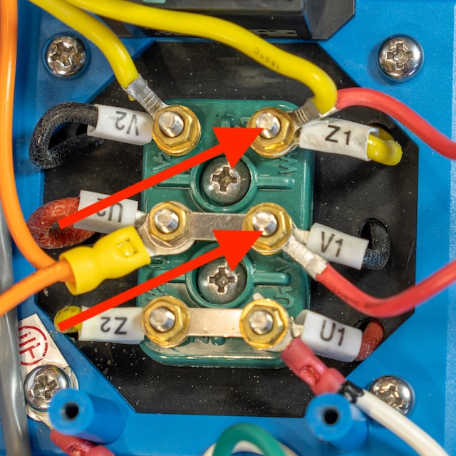
Wiring Block
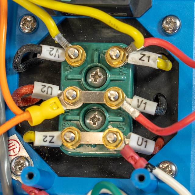
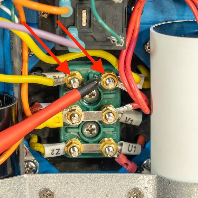
Between the start and run capacitors is a green wiring block. Each of the six connection posts is labelled and is connected as per the above schematic. Older systems may vary slightly from this and should not be updated from the original configuration.
Symptoms of Capacitor Failure
It is extremely rare for a run capacitor to fail, and even more rare for a start capacitor to fail. Other avenues should be exhausted before accessing the capacitor box. If a run or start capacitor fails, it will manifest itself in one or more ways, as follows.
Burning electronics smell – If the capacitor burns itself out completely, you may smell it.
Draws excessive current, possibly tripping the generator or breaker after a few seconds – If the run capacitor fails, the overall current and voltage will be significantly out of phase and the power factor decreases. This causes the system to draw more current than usual to generate the work required for the PSU to operate. If its running like this for too long, the motor windings will eventually overheat and burn out. The motor will then require replacement. This will most likely occur when operated from a large generator with a highly rated outlet.
Won’t start at all – Either the run or start capacitor failure may cause system to be difficult to start or not start at all. If the motor hums and doesn’t spin, the capacitor is definitely the first thing to check. Note that other things may cause difficulty in starting, such as a swollen impeller from being pickled for too long in strong solution.
Excessive vibration – If the run capacitor fails, the motor may vibrate excessively. Note that most vibration issues would be high pressure pump cavitation, which is much more common.
Replacement Capacitors
Rainman sells capacitors in a set, but they can be purchased from other sources. The recommended replacements may vary slightly from the original capacitance value installed in the motor. The voltage ratings can be as rated or higher.
115VAC / 60Hz Motor
Start capacitor: 300µF 125V
Run capacitor: 80µF 450V
230VAC / 50Hz Motor
Start capacitor: 100µF 250V
Run capacitor: 35µF 475V
Accessing Capacitors
-
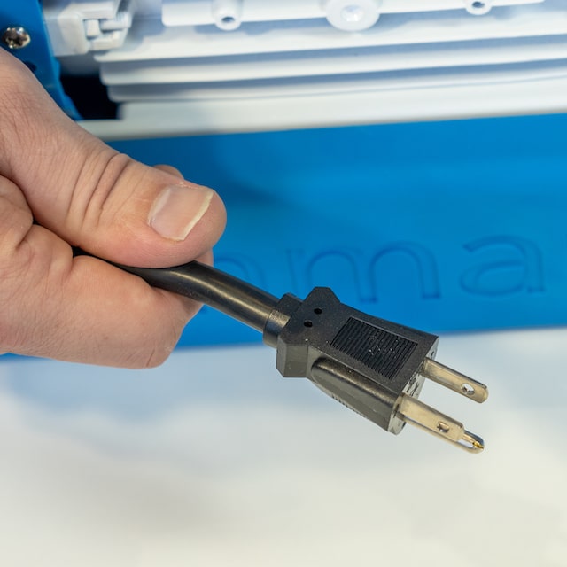
Before starting any procedure on the AC motor, ensure the system is unplugged from the power source. You should use an insulated electrician’s Phillips head screwdriver when working in the motor.
A 7mm socket wrench will be required for accessing the capacitor cables. A multimeter to test the capacitors may also be helpful.
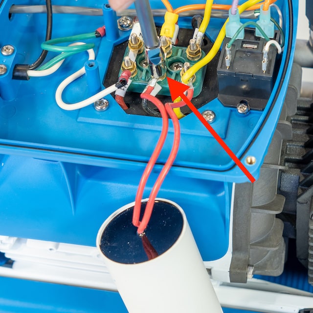
Capacitor Box
The plastic capacitor box sits on top of the white motor body. On older systems, it will be a black rectangular box and newer systems will be a shaped blue box.
The capacitor box on any Rainman Naked unit will be very easy to access as it is uncovered. On cased systems, you will need to remove the blue plastic shell. On Mk2 systems manufactured from January 2019, this can be done with a Phillips screwdriver. On the rotomoulded Mk1 systems, there is a separate procedure to remove the shell.
-
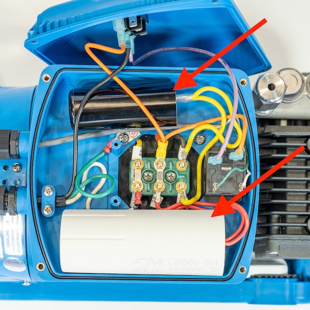
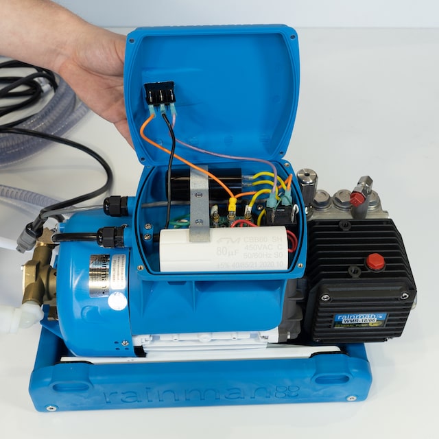
Remove four screws on top of the capacitor box to expose the internals. The capacitors are the two cylindrical components on either side of the capacitor box, which may be different colours than in the photos.

Discharge Capacitors
Capacitors are able to hold a charge, even when the system is unplugged. It is good practice to ensure they are discharged before working on the system.
-
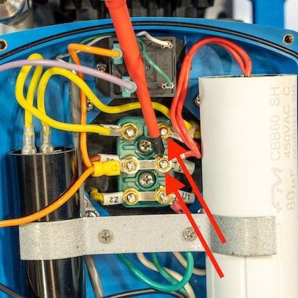
Use the electrician’s screwdriver to short the connection posts of the run capacitor. They are marked V1 and Z1. Ensure you do not touch metal contacts when discharging capacitors.
-
Use the electrician’s screwdriver to short the connection posts of the start capacitor. They are marked V2 and Z1.
The capacitors are now discharged and safe to handle.
Removing Capacitors
-
Remove the two screws holding the capacitor clamp in place.

-
The two capacitors can now be removed from the capacitor box.

Disconnect Run Capacitor
-
The run capacitor is connected to posts V1 and Z1.
-
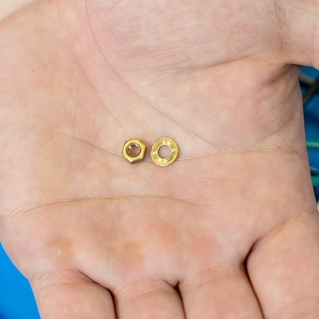
Use a 7mm socket to remove the bolts and washers on the posts V1 and Z1. They are small, so ensure not to lose them.
-
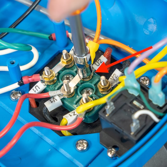
Loosen the bolt of the connection bar that is connected to post U2 so the run capacitor connection can be removed. This allows the run capacitor to be completely removed.
Note that on some older systems, the connection bar may be configured differently, negating the need for this step. Do not modify the original configuration of your particular wiring block.

Disconnect Start Capacitor
-
The start capacitor is connected to posts V2 and Z1. Remove the bolts and washers to access and remove the start capacitor.

Testing Capacitors
-
If a capacitor appears burnt or deformed, it has failed. If it appears undamaged, a multimeter with capacitance function is the best way to test. Follow the instructions of that multimeter to determine if capacitor is functioning correctly.
If you have a multimeter without a capacitance function, it may still be possible to use it for basic capacitor testing using the ohmmeter function. A failed capacitor will usually be an open circuit (infinite ohms reading). When a functioning capacitor is connected to a simple DC signal, such as an ohmmeter, it will briefly act like a short (zero ohms) with an exponential increase to an open circuit (infinite ohms) . If you set your digital ohmmeter to a range somewhere around 100kΩ and connect the capacitor, it will initially read a very low resistance, then rapidly increase towards infinity. All ohmmeters are different, but see image for how this might appear.

Reassembling System
-
Reassemble the system in the same manner it was disassembled. Note the following points:
– The replacement capacitors may be different rating, colour, and/or size to the originals.
– The capacitors are not polarised, so it is unimportant which lead connects to the post.
– Ensure the replacement capacitors are secured into the capacitor box. If they are still loose in the clamp, secure them with double sided foam tape or silicone type adhesive.
– Ensure the rubber seal around the perimeter of the capacitor box is correctly positioned when replacing the lid.