Create PDF To Save Offline
Rainman Technology Pty Ltd
49 Orchard Road
Brookvale, NSW 2100
Australia
www.rainmandesal.com
support@rainmandesal.com
Introduction
The Rainman control panel provides a remote control capability for any installed AC or 12VDC electric Rainman watermaker. This manual guides the installer through the control panel installation and provides details on how it affects use of the watermaker. It can be used for either brand new Rainman watermaker installations, or for retrofitting the control panel to existing installs.
This guide supplements the general operation, installation and autoflush manuals. It is highly recommended that you study this entire manual before planning and executing your control panel installation.
The panel itself is made of durable injection moulded, UV resistant, ASA acrylic. In addition to a convenient remote control capability, the panel incorporates additional capabilities to enhance the owner experience.

Types of Installations
New Installation – Naked Configuration
If the Rainman control panel is purchased with the Rainman Naked electric watermaker, the present model systems are designed to work together with minimum effort.
Retrofit Options
Click here to toggle details of retrofitting to existing naked or cased system


Retrofit Installation – Cased System
If you have installed a Rainman watermaker in the classic blue case configuration, you can use the control panel. There will be some parts required for compatibility.
A compatibility kit is required as well as some minor modifications to allow for the remote control.
The first issue is that the valve/gauge configuration is slightly different and an additional high pressure hose will be required for remotely locating the control at the control panel.
Secondly, the panel switch triggers a relay for the main pressure supply unit (PSU) power. For an AC watermaker, this will be a compatibility box.
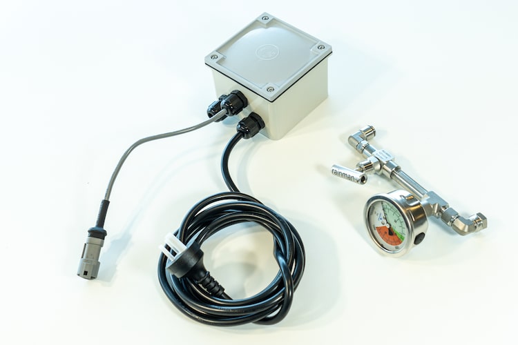
AC Case Compatibility Kit
Valve/gauge control assembly, high pressure hose, and a relay box.
12VDC Case Compatibility Kit
Valve/gauge control assembly and a high pressure hose.
Retrofit Installation – Naked Configuration
If the control panel is to be retrofitted to an existing Rainman Naked configuration, a compatibility kit will also be required. The compatibility kit is similar to that as described above for the cased systems, but there is no need for the high pressure hose.
AC Naked Compatibility Kit
Valve/gauge control assembly and a relay box.
12VDC Naked Compatibility Kit
Valve/gauge control assembly.
Installation Overview
There are three components to installing the Rainman control panel.
- Physical installation – The panel can be flush mounted, used with the included enclosure box as a standalone control unit, or used with our optional hatch mount for external installation.
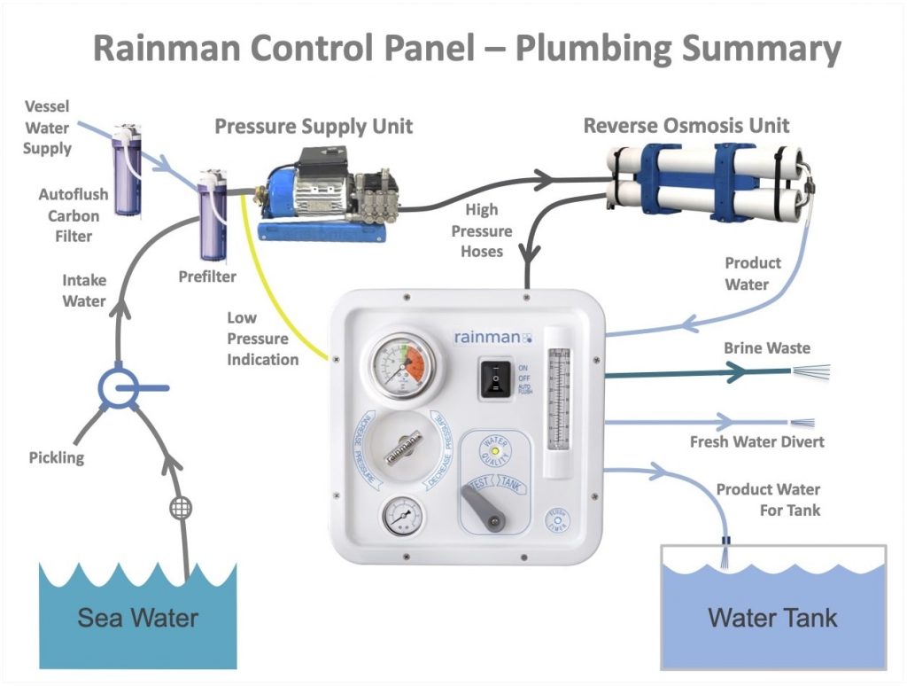
- Plumbing – Six total plumbing lines are required for the installation. One high pressure hose, a brine waste line, three product water hoses, and a line to the prefilter.
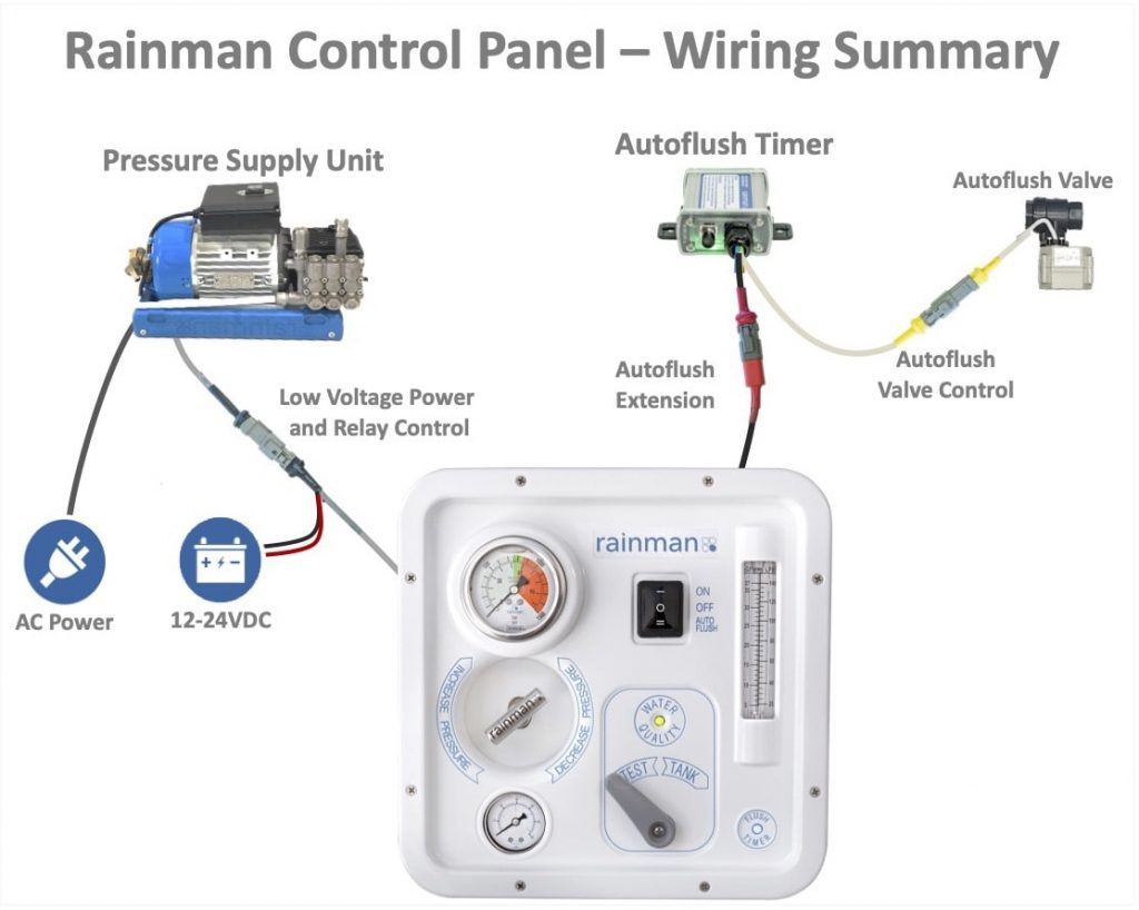
- Electrical – There is one mandatory electrical connection to the PSU (or compatibility box). This provides 12-24VDC power for the panel itself to operate and also controls a relay to switch either the AC or 12VDC PSU. If you have the optional autoflush system, there is another electrical connection to power the flush timer.
The diagram shows the plumbing and electrical connections for the control panel.

Physical Installation
A few principles apply to any of the three installation options in this section.
- Don’t mount the control panel above any electrical equipment.
- Although the acrylic control panel is UV resistant, it should not be mounted where it is in regular direct sunlight.
- The control panel should not be exposed to water spray.
- Try to position the panel so all plumbing and wiring come from underneath to minimise water ingress.
- Run all plumbing and cabling lines before doing any cutting.
Flush Mounted
If you intend to flush mount your control panel into a flat surface, you will need the following space available.
- Panel: 280 x 280mm (11″)
- Cutout: 250 x 250mm (9.9″)
- Depth behind panel: 155mm (6.1″)
The enclosure box is optional for use with the flush mounted panel. It can be used to keep the hoses and cabling tidy, but is not mandatory. If you do wish to use it, you will need physical access to the rear of the surface you are mounting the panel to.
Use the included paper template and a jigsaw to cut the main square hole. Four holes on the paper template should only be used if you are mounting the enclosure box in the rear of the control panel. These holes should be 4.5mm (3/16″) countersunk holes.
For the eight mounting holes in the control panel face, it is best to use the panel itself as a template to drill the 3.2mm (1/8″) holes.
If using the enclosure box behind the flush mounted control panel, read the Standalone Enclosure Box section as well.
Standalone Enclosure Box
If you do not have sufficient surface area for flush mounting the control panel, it is possible to mount the enclosure box to create a standalone control panel. The enclosure box itself can be rotated to be mounted on the bottom, either side, or top of the control panel. Use the box itself as the drill guide, and supplement the installation with Sikaflex (or similar).

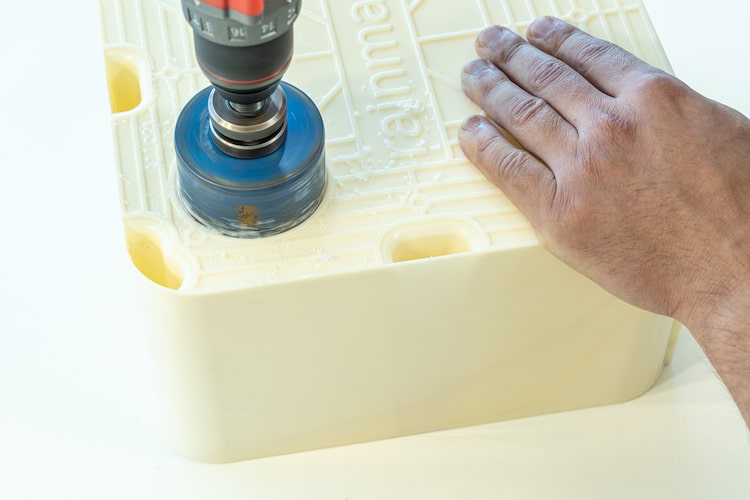
Use a hole saw to cut a hole in a convenient location for routing the plumbing and cabling. Circular guides are provided in the enclosure box mold, but you may drill holes wherever convenient. We recommend approximately 70mm (2 ¾”), but other sizes may suffice. Cut black edge bead to length and install inside drilled hole edge. This will protect the black high pressure hose from rubbing on the edges due to vibration.
If it assists in plumbing and cabling routing, cut multiple holes into the enclosure box.


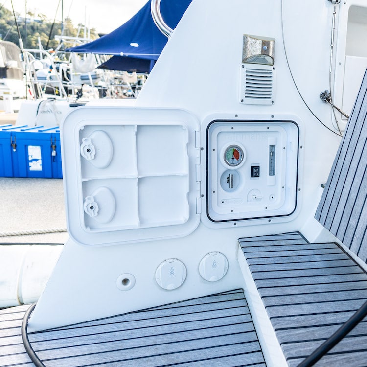
External Hatch
If you have a need for the control panel to be mounted externally, such as in a cockpit, Rainman offers an optional exterior hatch with an acrylic adapter. The dimensions will be:
- Hatch: 380 x 380mm (15″)
- Cutout: 305 x 305mm (12″)
- Depth behind panel: 185mm (7.3″)
If using the exterior hatch, it is also recommended to install the enclosure box to protect fittings at the rear of the panel. Mounting are pre-drilled to attach the enclosure box to the hatch. The enclosure box fits through the hatch hole, so access to the rear of the mounting surface is not required.
Plumbing Connections
Six plumbing lines are required for the control panel installation. It is highly recommended to run all lines before connecting to the fittings at either end.
- Black high pressure hose runs from the reverse osmosis (RO) unit.
- Green brine waste hose runs overboard.
- Yellow static pressure line tees into the prefilter outlet line, before the black high pressure pump.
- Three product water hose lines.
- From RO unit outlet.
- To fresh water tank
- To waste overboard
The other major line in an installation is the source water intake and related 3-way valve. This does not affect the control panel operation, so is discussed in the general installation guide.
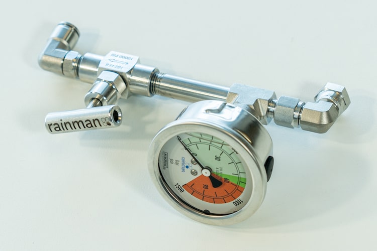
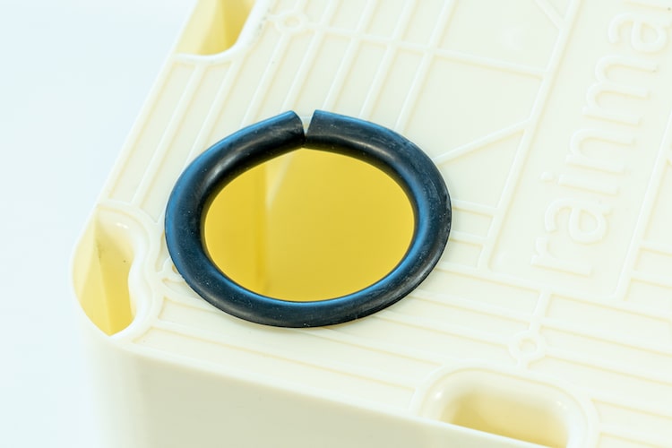
High Pressure Hose and Valve / Gauge Assembly
The valve/gauge assembly secures into the rear of the control panel via a clasp with two halves. This is one of the pieces that must be assembled by the installer.
- Thread the valve/gauge assembly through from the pressure supply unit (PSU) to the control panel. If you need to feed the HP hose through a small hole, see section below about the high pressure fittings.
- Place the valve/gauge assembly in one side of the clasp.

- Place the other half of clasp and secure with three screws.

- Insert assembly into rear of control panel, with gauge nearest the corner of the control panel.
- Secure assembly into the panel with four screws.

High Pressure Hose Fittings
It is unlikely to require changes to high pressure fittings. Three exceptions exist.
- The high pressure hose needs to be threaded through a narrow opening.
- The angle of the high pressure hose exiting the enclosure box needs to be changed.
- The control panel is being retrofitted to an existing installation or cased system.
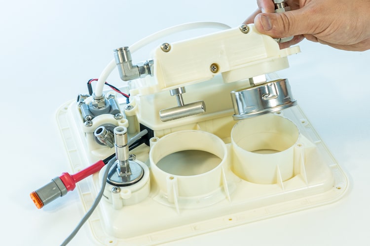
Click here to toggle details of high pressure fitting adjustments


These images are shown against a white surface for clarity. In practice, the adjustments may be made while the valve / gauge assembly is mounted in the control panel.
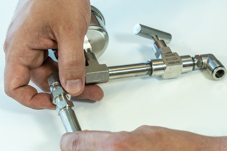
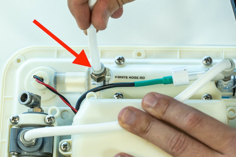
Change angle of HP hose on back of control panel
To change the angle that the HP hose exits the control panel, loosen the nut shown in photo by only half of a turn using a 16mm spanner (wrench). Set the desired angle for HP hose. While holding the hose in place, retighten the nut a half turn, using about the same amount of strength that was required to loosen it.
Retrofit new valve/gauge assembly (compatibility kit)
or
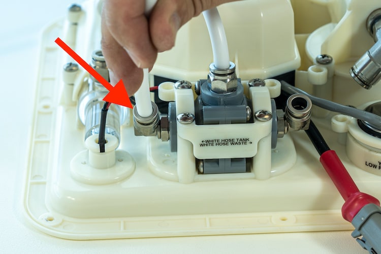
Thread HP hose through narrow hole
For either of these actions, you will utilise the hydraulic nut and cone fitting between the black HP hose and the elbow near the pressure gauge. To tighten correctly, make it finger tight, then use a 16mm and 18mm spanners (wrenches) to tighten the fitting an additional 35°- 45° or 1/8 of a turn, so it is very snug.
If retrofitting new valve/gauge assembly, the old valve/gauge assembly will be orphaned and unutilised.
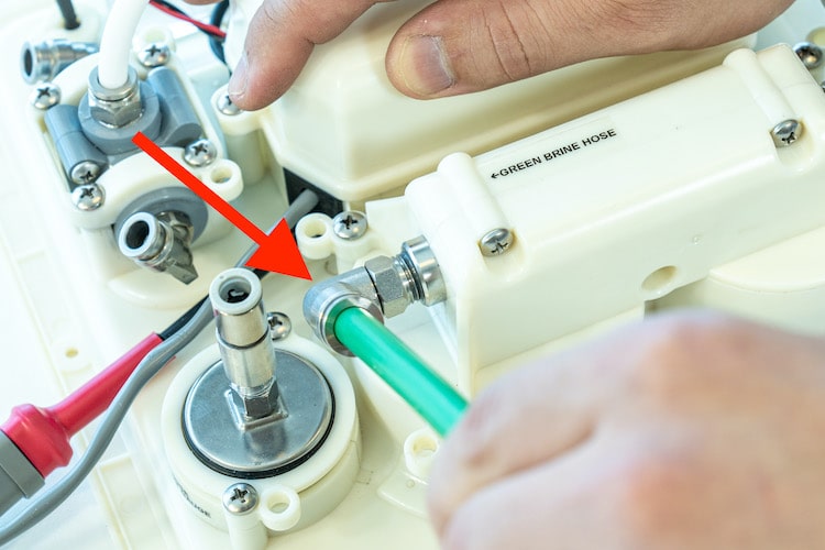
Brine Waste Hose
Cut the 10mm green brine waste hose to length and attach it to the pushfit fitting.
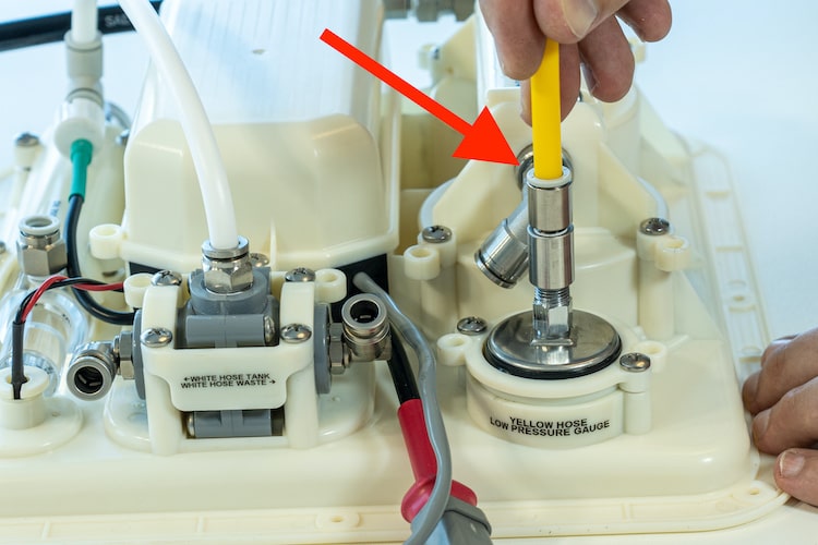
Low Pressure Gauge Hose
The yellow low pressure gauge hose connects at one end to the control panel gauge and the other end gets spliced into the prefilter outlet.
Control panel connection
Cut the 8mm yellow hose to length and attach it to the pushfit fitting.
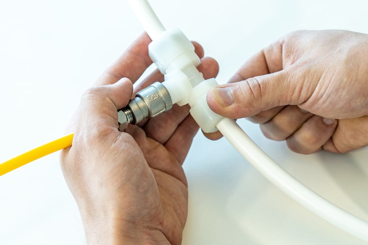
Prefilter outlet connection
- Cut the 1/2″ white hose between the prefilter and the high pressure pump, closer towards the prefilter.
- Attach the 8mm yellow line to the pushfit fitting on the tee.

- Connect both sides of the tee to the cut white prefilter lines. To properly tighten the fittings, loosen nuts on both sides by two turns. Press the hose into the fitting past the initial friction of the o-ring so a solid seat is achieved. Then finger tighten both nuts. There is no need to overtighten this as the seal is created by the o-ring.
Product Water Hoses
Three product water hoses connect to the control panel. One is from the RO unit and two flow out from the control panel to either the tank or overboard. These are all 8mm white hoses. A white 8mm bridging hose that flows from the top of the flow metre to the product water three way valve is preinstalled.
RO hose
This is the product water input to the control panel that is supplied from the reverse osmosis (RO) unit.
Cut the 8mm white hose to length and attach it to the pushfit fitting at the inlet to the flow metre.
Tank hose
This hose routes water to the tank after the initial operation and water has been measured pure.
Cut the 8mm white hose to length and attach it to the pushfit fitting on the tank side of the three way valve outlet.
Divert hose
This is the hose to direct the product water out to waste during the initial watermaker operation, until the “old” water or pickle solution is washed out of the system and the water is pure.
Cut the 8mm white hose to length and attach it to the pushfit fitting on the divert side of the three way valve outlet.

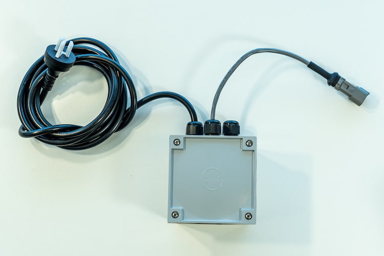
Electrical Connections
The control panel is powered by 12-24VDC, so there is no high voltage wiring, even for AC systems. Each control panel will have only two electrical connections. One is a 12-24VDC powered cable from the pressure supply unit (PSU) that triggers a relay to turn the PSU on. The other is if you have the optional Rainman autoflush system for your watermaker. This lead provides power to the flush timer and provides an extension for the timer LED indicator.
The power relay line will vary depending on the PSU configuration and whether it is a naked or cased system.
AC System
The control panel has a 5 metre (16′) grey cable with black heat shrink and a male triangular Duetsch plug.
The red and black wires should be connected to a 12-24VDC power source. This provides power for the control panel. We recommend using a breaker/fuse rated between 2 and 5 amps.
The Duetsch plug is to be connected to the matching socket on the PSU. This allows the control panel switch to trigger the low voltage relay and power the PSU.
AC System - Cased Configuration or Retrofit
Click here to toggle details of retrofitting to existing naked or cased system
If the control panel is to be connected to a cased PSU or retrofitted to an older PSU, the compatibility box holds the relay for controlling the PSU power.
Connect the three AC power wires as per the wiring diagram on the side of the box itself.
Plug the compatibility box into an AC power source.
The triangular socket on the compatibility box is to be connected to the matching Duetsch plug on the control panel.
12VDC Systems
All 12VDC control panels will include a relay with a triangular socket on one end and red battery cables on the other. Connect the socket to the matching Duetsch plug on the control panel. Connect the red cables in line with one battery wire of the 12VDC PSU.
The relay can be physically mounted anywhere that is convenient. On a naked configuration, we recommend that be in the motor cowling.
The red and black wires on the Duetsch plug should be connected to a 12-24VDC power source. This provides power for the control panel.

Autoflush Option
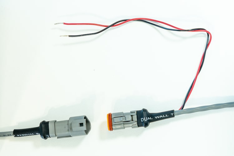
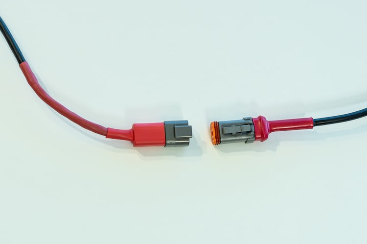
The control panel is compatible with version 1.2 (or later) of the Rainman autoflush timer. Older versions of the autoflush will need to have the flush timer box replaced to be compatible with the control panel. Version 1.2 flush timer has an electrical cable with a square red Duetsch plug on the end. This lead allows the timer to be powered by the control panel and has wiring for an extension of the blue indicator LED.
Plug the male square red Duetsch plug from the flush timer box into the corresponding female side on the control panel.
Operational Differences When Using Control Panel
Salinity Sensor
The Rainman control panel has an integrated salinity sensor to indicate the water quality. It incorporates a salinity probe and related electronics to power a tri-colour LED to be green, yellow, or red.
Normal operating procedure is to have the product water three way valve set to “Divert” when you start your system. Pressurise the watermaker as per normal operating procedures. When the water quality LED turns yellow or green, the product water has sufficiently low total dissolved solids (TDS) and the product water valve can be switched to “Tank”. At this point, product water is flowing into the vessel’s water tank.
LED colour:
- Red – High TDS – Consider not using the product water. It is expected that the LED will be red for at least a minute from when water is being made. This is to flush the stale product water or pickle solution out of the watermaker. If it stays red, there is a TDS issue to resolve. This may be related to worn RO membranes or a mechanical issue with your watermaker.
- Yellow – Medium TDS – Product water has slightly higher than normal TDS, but is within operating range. If the LED stays yellow for an extended period of time, there may be a minor mechanical issue or the RO membranes may be ageing. If this is due to the membranes ageing, consider changing them within the next year.
- Green – Good TDS – A normally operating system with young membranes and operating in seawater should reach green within two minutes of reaching full pressure. The system is operating within specification for water purification. It is not a comprehensive indicator that everything is perfect within your watermaker.
- Off – No TDS reading – Either extremely pure water is flowing through the system or no water at all is flowing. This may commonly indicate that the system has not been pressurised yet.

Tank Divert Valve
This three way valve controls the flow of product water. The system should always be started with the valve set to Test (Divert) when the water is being diverted overboard. After the water quality light changes from red to either green or yellow, the product water is sufficiently pure and the valve can be changed to send water to the vessel’s tank.

Fresh Water Flush Trigger
If the optional fresh water flush system is installed, the control panel adds some functionality. If the autoflush is not installed, the features described below sit without function.
The power switch on the control panel has more function than the simple on-off switch on the pressure supply unit (PSU). The switch itself is powered by 12-24VDC and it controls a relay located either in the PSU capacitor box or the compatibility kit.
ON – The PSU is powered and the motor will be running. At the same time, the autoflush timer box gets unpowered, so it is not possible for a flush cycle to initiate while making water.
OFF – The PSU is off and the autoflush is not enabled.
AUTOFLUSH – A flush cycle will be triggered and then the flush timer will be set for a seven day cycle.

The blue flush timer LED is effectively an extension of the blue LED in the flush timer box. It will not be illuminated during water making or when the system is off. When the control panel is switched to autoflush, the blue LED will be flashing to indicate the number of days remaining until the next flush cycle.
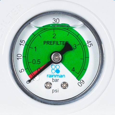
Low Pressure Gauge
This gauge is monitoring the pressure at the outlet of the prefilter. The actual reading of this gauge is not particularly important, so long as it reads at least 0.2 bar (2.5psi). This is the pressure required to feed the high pressure pump.
If the pressure drops below this level, it typically indicates one of three issues.
- Prefilter is getting dirty and restricting flow.
- Impeller is wearing and not providing sufficient pressure.
- There is a blockage in the intake stream.